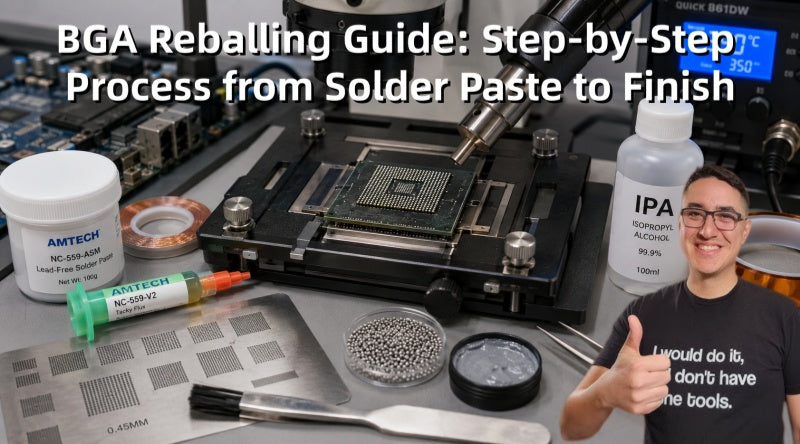
As smartphones, game consoles, and high-performance motherboards become increasingly integrated, BGA chips have become a standard core package. However, long-term heat exposure or physical impact can cause solder joint failures such as cracks or detachment, leading to issues like no power, random restarts, or display faults. This article briefly outlines the full process from chip removal and cleaning to reballing and reflow soldering.

I. Essential Tools and Materials Preparation
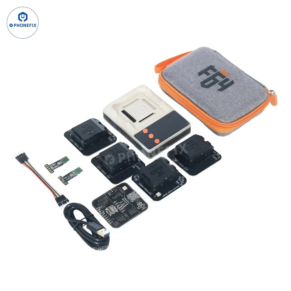
Before commencing the operation, ensure that you possess the following specialized tools; these are the prerequisites for ensuring a successful outcome:
1. Hot Air Equipment: A professional BGA rework station (recommended) or a combination of a "preheater + high-quality hot air gun."
2. BGA Stencil: Must precisely match the pin configuration of the specific chip model being serviced.
3. Soldering Medium:
· Solder Balls: Classified as leaded (easier to work with, lower melting point) or lead-free (environmentally friendly, higher melting point).
· Solder Paste: Used for direct stencil printing during the reballing process.
4. Flux: High-quality, viscous paste flux (Tacky Flux), used to secure the solder balls in place and facilitate proper fusion.
5. Cleaning Tools: Isopropyl Alcohol (IPA), lint-free cloths, and cotton swabs.
6. Desoldering Tools: Soldering iron (with a knife or hoof-shaped tip) and high-quality desoldering wick.
7. Auxiliary Equipment: Reballing jig/fixture, high-magnification microscope or magnifying glass, tweezers, and Kapton tape (high-temperature resistant tape).
II. Step-by-Step BGA Reballing Process
Step 1: Component Removal and Surface Cleaning
1. Chip Removal: Secure the PCB onto the rework station. Configure the temperature profile according to the dimensions of the chip, and apply heat evenly. Once the solder reaches its melting point, use a vacuum suction pen or tweezers to gently lift the chip vertically.
2. Removal of Old Solder (Desoldering/Deballing): Apply an appropriate amount of flux to the solder pads located on the underside of the chip.
· Use desoldering wick in conjunction with a soldering iron. Lay the desoldering wick flat against the solder pad, then gently slide a soldering iron over it; the residual solder will be drawn away via capillary action.
· Note: Perform this action gently; do not apply excessive pressure, as this may scratch the pad surface or cause the pads to lift (detach).
3. Chip and PCB Cleaning: Use isopropyl alcohol and a lint-free cloth to repeatedly wipe the chip until the surface is free of any greasy residue and appears as clean and glossy as new.
· Inspect under a HD microscope to check for any lifted pads (pad detachment) or short circuits.
· Similarly, clean the corresponding pads on the PCB side.

Step 2: Reballing (The Core Process)
1. Apply Flux: Apply an extremely thin and uniform layer of flux to the surface of the cleaned chip. Applying too much flux can cause bubbles to form during heating, leading to solder ball displacement or shifting.
2. Stencil Alignment: Place the chip into a reballing fixture and position the stencil over it. Adjust the position to ensure that the apertures in the stencil are perfectly physically aligned with the pads on the chip.
3. Filling Method (Choose One):
· Solder Paste Method: Use a metal spatula to evenly spread solder paste across the stencil. Ensure that every aperture is filled, then scrape away any excess paste.
· Solder Ball Method: Pour solder balls of the appropriate diameter onto the stencil, then gently shake the fixture to allow the solder balls to automatically settle into the apertures.
4. Securing: If the stencil is thin—making it prone to thermal deformation during heating—it is recommended to use Kapton tape to secure its edges.
Step 3: Reflow Soldering and Final Inspection
1. Reflow Soldering: Use a hot air gun (a temperature setting between 330°C and 380°C is recommended, depending on the specific solder alloy composition).
· Maintain a consistent distance and heat the BGA Reballing Stencil evenly. Observe the solder paste as it changes color, or watch for the solder balls to "flash" (indicating melting); at this point, the solder will automatically self-align under the influence of the flux and form smooth, spherical balls.
2. Cooling and Demolding: After allowing the chip to cool completely (never attempt to forcibly separate it while still hot), carefully remove the stencil.
3. Quality Inspection: Conduct a comprehensive inspection under a microscope:
· Are there any missing solder balls?
· Is there any bridging (short-circuiting) between adjacent balls?
· Are the size and height of the solder balls consistent?
4. Final Cleaning: Use isopropyl alcohol to remove any residual flux, thereby preventing chemical corrosion and electromigration.

III. Key Secrets to Success and Important Considerations
· Uniform Heating is Paramount: Rapid localized heating can cause the stencil to warp, leading to solder ball bridging or poor connections. It is essential to use a preheating station and to raise the temperature gradually.
· Solder Pad Protection: The cleaning process is when the chip is most vulnerable. When using desoldering wick, ensure sufficient flux is applied; use a gentle, gliding motion—rather than brute force—to avoid lifting the tiny solder pads from the PCB or chip.
· Alignment Precision: Even a deviation of just 0.1mm can result in the complete failure of the reballing process. Using a high-quality reballing fixture can significantly improve the process's tolerance for error.
· Absolute Cleanliness: Any minute dust particles or residual old flux will compromise the adhesion of the new solder balls. It is imperative to maintain a dust-free working environment.
BGA reballing is a micro-soldering process that places extremely high demands on equipment, technical skill, and experience. As smart devices continue to evolve toward higher levels of integration, BGA rework technology has become an indispensable capability for high-end motherboard repair. Only by combining high-quality mobile phone repair tool kits with standardized operational procedures can one truly achieve stable, high-quality BGA repair results.