Today we separates the motherboard of iPhone 13 Pro and compare with iPhone 12 Pro to view its interior structure. Through separate and recombine the motherboard, we are going to share motherboard differences and repair difficulty.
Use Infrared Thermal Camera to benchmark iPhone 13 Pro and iPhone 12 Pro at the same time.

We found that iPhone 13 Pro gets hotter than iPhone 12 Pro. iPhone 13 Pro can reach a maximum temperature of around 48 °C while the maximum temperature of iPhone 12 Pro is around 40 °C.

Then we will find out what has caused the overheating.
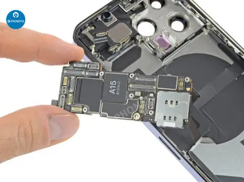
Remove screws with screwdriver.Separate the motherboard and iPhone 13 Pro's motherboard is designed to be more compact, and it no longer uses an L-shaped design, leaving more room for the battery.
Remove the motherboard. SIM card reader is welded to the motherboard. It is a double-layered design motherboard. For better heat dissipation, both sides of the motherboard are covered with thick heat dissipation tapes.
Remove tape on the motherboard and we can find NAND is under the A15 tape. Remove tapes on the back of the motherboard with tweezers. Heat dissipation tapes on the motherboard are reusable.
There is components on the back of iPhone 13 Pro’s signal board. Use a universal heating platform at 170 °C for separation. Heat around the motherboard with Hot Air Gun, when the temperature of the Heating Platform reaches 150 °C, the logic board becomes loose. Remove the logic board with tweezers.
Remove thermal grease on the chips. A15 is bigger than previous models, which makes CPU desoldering more difficult. iPhone 13 Pro's baseband CPU is the Qualcomm X60.
Check whether a single logic board of iPhone 13 Pro can trigger the boot-up.
Power the logic board with a Direct Current Supply. Connect the display and trigger the boot-up with tweezers. iPhone 13 Pro took 8-10 seconds for the Apple logo to appear on the screen, which is longer to trigger the boot-up than previous models.
Recombine the signal board with the logic board. Apply some Paste Flux to the bonding pads of the signal board and use some low-temperature Solder Paste to neutralize the temperature of the bonding pads. Clean the bonding pads with Soldering Iron and solder wick.
Apply solder paste to the bonding pads of the logic board and lean the bonding pads with PCB Cleaner.
Reball the signal board and attach the signal board to the Reballing Platform. Put the reballing stencil in position. Apply middle-temperature Solder Paste evenly.
Remove the reballing stencil. Put the signal board on the Heating Platform to heat. After the solder balls are formed, cool the signal board. Apply some Paste Flux to the bonding pads. Align the logic board with the signal board. Add heat around the motherboard with Hot Air Gun.
After the motherboard has cooled, detach the motherboard and reattach foam and heat dissipation tapes to the motherboard. Install the motherboard for testing.
This is the motherboard chip distribution diagram of iPhone 13 Pro.
In the process it is found that iPhone 13 Pro still has a double-layered motherboard. There are some changes in motherboard appearance but main chip distribution is little change.
Besides, the CPU is stacked with baseband, which makes the motherboard heat up easily and increases the difficulty of repair.
Notes:
1. Remove tape on the motherboard with YIHUA 8509 Hot Air Gun at 100 °C.
2. Please do not damage the tapes during repair to avoid influencing the heat dissipation effect after assembly.
3. Pay attention not to damage the components while separating.
4. Please do not affect surrounding components while applying solder paste. This should also be noted while using Soldering Station to remove tin.