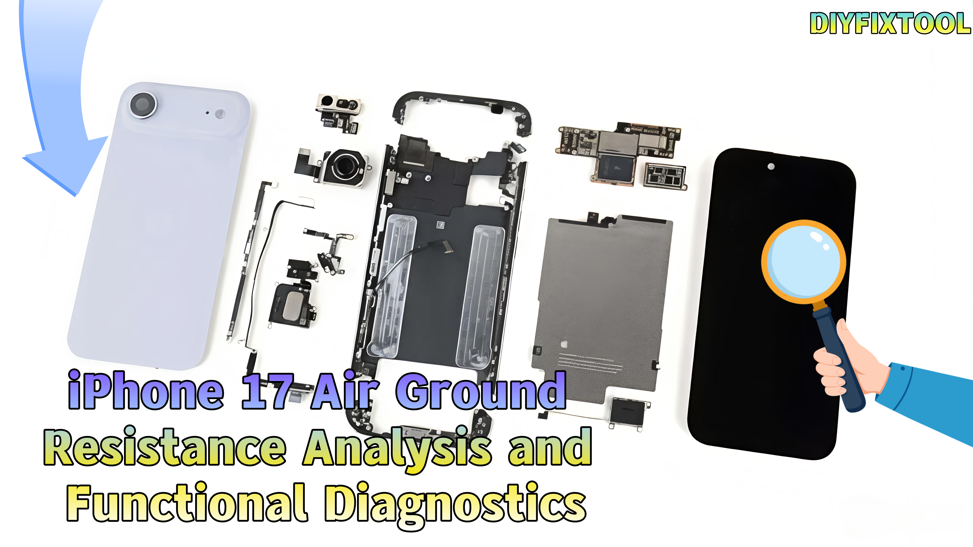
With the release of the iPhone 17 Air, its precise design and performance have drawn attention. The ground resistance values of its mainboard connectors have become a key focus for repair engineers and tech enthusiasts. These diagrams offer insights into the hardware design and serve as valuable references for repairs. DIYFIXTOOL will analyze the ground resistance values and their functions on the iPhone 17 Air's mainboard.

I. Importance of Ground Resistance Diagrams
The quality of electrical connections affects performance and stability. Measuring ground resistance between connectors and the mainboard ground lets repair engineers quickly spot faults. For example, a resistance of "OL" indicates an open circuit, while "482" denotes 482 ohms, providing useful diagnostic clues.
II. Mainboard Interfaces and Functional Analysis
Next, we'll dive into the key connectors and their functions on the mainboard for efficient diagnostics and repair:
1. Battery Connector
· Hardware Structure: Located at the upper left of the mainboard, with a multi-pin metal connector that connects to the iPhone battery via a ribbon cable.
· Functional Logic: "GND" is the ground pin, ensuring stable current; "420", "310", and "720" correspond to voltage, charge detection, and health feedback, respectively.
· Repair Value: Can detect pin voltage/signals to determine whether the issue is with the battery or the mainboard connector, such as "not charging" or "battery health issue."

2. Antenna Interfaces
a. Upper Antenna Interface
· Hardware Structure: Located at the upper and middle edges of the mainboard, small metal connectors connected to external antennas.
· Functional Logic: "GND" shields interference; "510", "600", and "490" handle 5G and mid-frequency signals; "0L" detects faults. Abnormalities can cause signal loss.
b. Lower Antenna Interface
· Hardware Structure: Located at the bottom edge of the mainboard, connected to Bluetooth, Wi-Fi, and NFC antennas.
· Functional Logic: "470" and "500" correspond to Bluetooth 5.0 and Wi-Fi 6E signals. Abnormalities can lead to "Bluetooth not connecting" or "Wi-Fi dropping."
c. mmWave Antenna Interface
Hardware Structure: Located slightly to the middle at the bottom of the mainboard, with high-density pins connected to the mmWave antenna.
Functional Logic: "2175", "350", and "270" correspond to mmWave bands (above 24GHz), ensuring gigabit speeds; "0L" detects faults. Abnormalities can cause a drop in speed.

3. Infrared (Iris) Transceiver Interface
Hardware Structure: Located at the upper left of the mainboard, with fine metal contacts connected to the iris recognition module.
· Functional Logic: "350", "530", and "510" control infrared light emission strength, sensitivity, and data encoding; "400", "430" transmit iris encoding data.
· Repair Value: Can detect infrared signal pins to determine if the iris recognition module is functioning properly. Additionally, an Infrared Thermal Camera can be used to locate any overheating or faulty connections in the area, aiding in diagnosis.
4. Sensor Interface
· Hardware Structure: Located at the lower middle of the mainboard, with multi-pin connectors for connecting accelerometers, gyroscopes, and ambient light sensors.
· Functional Logic: "350", "670", "580", "340", and "660" correspond to sensor signals like acceleration (screen rotation, motion) and ambient light (brightness). "GND" ensures stability; abnormalities may cause "brightness failure" or "motion issues."
· Repair Value: Can detect sensor signal pins to determine if the sensor module is functioning correctly.

5. Power/Shutter Button Interface
· Hardware Structure: Located at the upper left of the mainboard, with a multi-pin connector for the power and camera shutter buttons.
· Functional Logic: "340", "325", and "750" correspond to power and camera triggers; "GND" ensures stability. Abnormalities can cause "button failure" or "false triggers."
· Repair Value: Detects pin signals to help diagnose "unresponsive buttons" due to hardware or connection issues.
6. Tailpiece Connector
· Hardware Structure: Located at the upper left of the mainboard, with high-density connectors that link the charging interface (Lightning) and tailpiece ribbon cable.
· Functional Logic: "GND" ensures stable charging and data transmission; "1700" and "1770" are fast charging pins (27W/35W); "270", "650", and "680" handle USB 2.0 data transfer; "350" and "670" are for Lightning audio.
· Repair Value: Detects pin signals to diagnose issues like "not charging," "unable to connect," or "no sound," helping identify if the problem is with the ribbon or connector.

7. Display/Touch-Screen Interface
· Hardware Structure: Located at the lower middle of the mainboard, with multiple pin connectors for the screen module (display + touchscreen).
· Functional Logic: "340", "560", and "600" correspond to display signals (resolution, refresh rate, color); "270", "370", and "670" are touch pins; "GND" and "0L" ensure stability. Abnormalities can lead to "screen not turning on," "flickering," or "touch failure."
· Repair Value: Detects display/touch signal pins to help diagnose if the issue is with the screen module.
8. Front Camera Interface
· Hardware Structure: Located at the front camera ribbon cable area, small metal connectors for the iPhone Front Camera (including Face ID infrared and depth-sensing cameras).
· Functional Logic: "525", "400", and "440" correspond to image signal transmission and encoding; "420" and "520" transmit Face ID depth information for 3D facial modeling.
· Repair Value: Detects front camera interface signals to diagnose "front camera not working" or "Face ID failure."

9. Infrared/Dot Matrix Interface
· Hardware Structure: Located at the front camera module ribbon cable area, connected to the Face ID dot matrix projection module.
· Functional Logic: "485", "630", and "680" control infrared dot matrix emission (building a 3D facial contour); "340", "345", and "530" are feedback pins for verifying projection accuracy.
· Repair Value: Detects dot matrix signals to determine if "Face ID is unable to recognize."
10. Button/Flashlight Interface
· Hardware Structure: Located at the lower right of the mainboard, small metal connectors for side buttons (volume, mute) and the rear flashlight.
· Functional Logic: "680" is the flashlight power/control pin (for flash and flashlight functions); "GND" ensures the button and flashlight loop is stable. Abnormalities can result in "volume button failure" or "flashlight not lighting up."
· Repair Value: Detects button and flashlight interface signals to help diagnose hardware faults.

III. Conclusion
By analyzing the ground resistance diagrams of the various connectors on the iPhone 17 Air's mainboard, we can see Apple's meticulous consideration in device design. When facing hardware failures, repair engineers can rely on the data in these diagrams to quickly pinpoint the fault, reducing repair time and costs. If you need high-quality repair tools, stay tuned to DIYFIXTOOL.