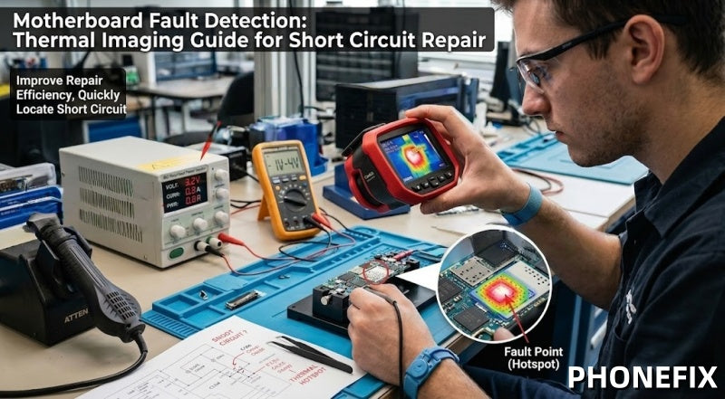
In modern mobile phone motherboard repair, highly integrated chips make traditional point-by-point troubleshooting slow and inefficient. Thermal imaging analysis, combined with a DC power supply, provides a fast and non-contact solution for leakage detection and short-circuit diagnosis, helping technicians quickly locate faults and improve motherboard repair efficiency.

I. Principles of Thermal Imaging Detection: Rapidly Pinpointing Short-Circuit Hotspots
When a short circuit occurs on a motherboard, current flows with abnormal concentration, causing local temperatures to rise rapidly. Using an infrared thermal imager, we can directly observe these "hotspot areas," allowing us to quickly identify the location of the faulty component—for instance:
· Localized heating caused by a short-circuited capacitor;
· Heating resulting from abnormal overcurrent through a resistor;
· Heating caused by an internal breakdown within an IC chip;
The greatest advantage of this approach—compared to traditional methods—is that it eliminates the need for repetitive component removal, enabling direct, visual localization of the fault point.
II. Repair Tool Preparation (Core Equipment)
In practical repair scenarios, a combination of the following three types of tools is typically required:
1. Infrared Thermal Imager (Core Diagnostic Device): Used to observe the PCB's thermal distribution in real-time and quickly pinpoint short-circuit hotspots.
2. Digital Regulated DC Power Supply: Used to provide a controlled power source to the motherboard while monitoring for thermal anomalies.
3. Power Test Cables (Boot Trigger Cables): Used to quickly connect to the mobile phone motherboard, facilitating a stable power-on test environment.
III. Steps for Short Circuit Localization Using Thermal Imaging
Step 1: Power-Off Inspection and Preliminary Assessment
· Confirm that the motherboard is completely powered off;
· Visually inspect for signs of burning, electrolyte leakage, or obvious physical damage;
· Use a multimeter to perform a preliminary check for the presence of a short circuit;
Step 2: Low-Voltage Power Injection
Use a DC power supply to inject a safe, low-voltage current into the motherboard:
· Voltage is typically controlled within the 1V–4V range;
· Current is limited to a safe range (to prevent secondary damage);
· Observe whether the current spikes abnormally (indicating a short circuit);
Step 3: Thermal Imaging Scan to Locate Hotspots
Turn on the thermal imager and perform a comprehensive scan of the motherboard:
· The short-circuit point will typically heat up rapidly within a few seconds;
· The location of the hotspot identifies the primary suspect component;
· This allows for the precise pinpointing of capacitors, ICs, or power modules;
Note: This is the most critical step in the entire thermal imaging analysis process.

Step 4: Faulty Component Detection and Confirmation
Perform further verification of the hotspot area:
· Measure the component's resistance value to check for anomalies;
· Check if a capacitor has failed (shorted/broken down);
· Determine if an IC has failed due to overheating;
Step 5: Repair and Replacement
· Use a hot air gun or BGA soldering station to remove the faulty component;
· Replace it with a capacitor, resistor, or chip of identical specifications;
· Clean the solder pads and resolder the new component;
Step 6: Retesting and Verification
A secondary verification is mandatory after the repair is complete:
· Power on the device again and observe whether the current returns to normal levels;
· Use the thermal imager to confirm that no abnormal hotspots remain;
· Ensure that the short circuit has been completely eliminated, allowing for stable operation;
III. Best Practices and Optimization Tips
To achieve the most precise detection results, please adhere to the following professional recommendations:
1. Optimize Camera Settings: Adjust the resolution and focus of the infrared camera according to the size of the motherboard. Appropriate contrast adjustments can help you accurately distinguish heat sources amidst densely packed components.
2. Voltage Limitation Principle: When performing voltage injection, always start with a low voltage and increase it gradually. Never inject a high current exceeding the motherboard's rated operating voltage, to prevent secondary damage to functional chips.
3. Comprehensive Diagnosis: Thermal imaging should be used in conjunction with a multimeter and the circuit schematics. First, identify the characteristics of the short circuit; next, utilize thermal imaging to pinpoint the exact location; finally, cross-reference the schematic diagrams to analyze the associated circuitry. Only by following this sequence can the highest rate of repair success be achieved.
IV. Safety Precautions (Strictly Mandatory)
Electronic repair carries inherent risks; please observe the following:
· You must wear an anti-static wrist strap.
· Avoid directly injecting high voltage into the motherboard.
· Maintain a dry and clean working environment.
· Take precautions to prevent the hot air gun from inadvertently damaging surrounding components.
As smartphone motherboard structures become increasingly complex, traditional repair methods are no longer sufficient to meet the demands for high-efficiency servicing. Consequently, thermal imaging technology—combined with low-voltage power injection testing—is rapidly emerging as the industry-standard solution. Mastering the methodology of "thermal imaging analysis + leakage detection"—and integrating it with professional mobile repair toolkits and standardized operational procedures—will not only significantly boost repair efficiency but also enable more stable and reliable fault diagnosis capabilities.