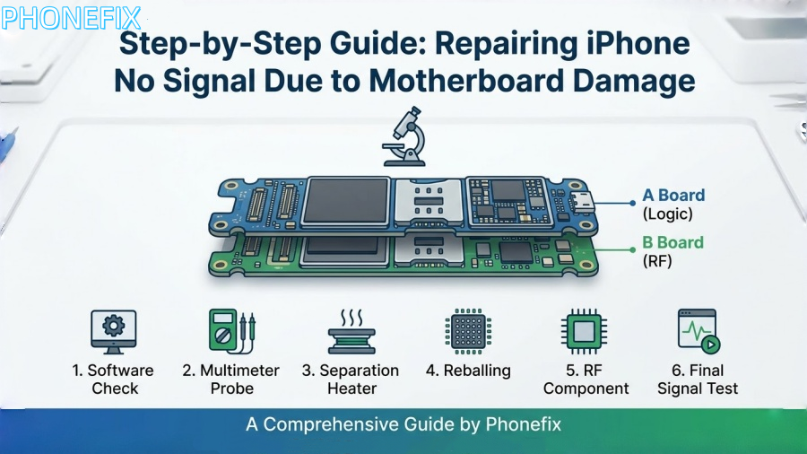
In the field of smartphone repair, the “No Service” or “Searching” issue on iPhones is one of the most challenging problems. This is particularly true for models since the iPhone X series, as Apple has adopted a dual-layer stacked motherboard design (commonly referred to as the “sandwich” structure). While this design saves space, it also complicates repairs. When the phone experiences physical shock (such as a drop) or moisture exposure, the solder joints between the two layers of the motherboard are prone to cracking, leading to interrupted baseband signal transmission. In this guide, Phonefix will walk you through the diagnostic logic and detailed repair steps for fixing iPhone signal loss caused by motherboard damage.

I. Fault Diagnosis: Identifying the Root Cause of Signal Failure
Before reaching for a soldering iron or hot air gun, a systematic software and peripheral diagnosis must be carried out to confirm that the problem lies with the motherboard hardware.
1. Software Logic Validation
First, enter the dialer screen and input *#06#.
· Normal case: The screen should immediately display the device’s IMEI number.
· Fault symptoms: If nothing appears or only a blank screen shows, this typically means the CPU cannot recognize the baseband chip (Baseband IC), or the baseband firmware (Modem Firmware) is corrupted.
Tip: Additionally, navigate to “Settings” -> “General” -> “About” and check the “Modem Firmware” section. If it is blank, it can be conclusively determined as a baseband circuit fault.
2. Cross-Checking Associated Features
Given the dense distribution of solder joints in the iPhone’s middle layer, signal issues often accompany other malfunctions. Check if the Wi-Fi and Bluetooth toggles are grayed out (unable to turn on). If both signal and Wi-Fi fail simultaneously, this is a typical indication of a “mid-layer crack” in the dual-layer motherboard, suggesting the communication bus between the top and bottom layers has been severed.
3. Physical and Electrical Testing
After disassembling the device, connect the motherboard to a DC power supply and observe the current fluctuations on boot-up. If the current jumps unusually high or remains fixed at a particular value, it may indicate a short circuit in the baseband power IC. Under a microscope, check the edges and corners of the motherboard for deformation or cracks, especially in phones that have been dropped, as the middle layer solder joints often show subtle breakages.

II. Professional Tools Needed for the Repair
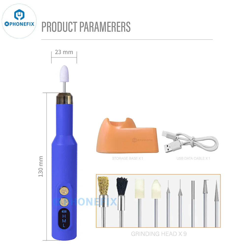
This type of repair, requiring micron-level precision, demands high-quality tools to ensure success:
· High Magnification Microscope: At least 7-45x continuous magnification, used to inspect small solder pad peeling.
· Smart Heating Platform (Preheater): Equipped with precise temperature control for layer separation and re-joining of dual-layer motherboards.
· Hot Air Rework Station: Used for disassembling baseband CPU and other small components such as inductors and capacitors.
· High-Precision Multimeter: Used to measure ground resistance and locate short circuits.
· Infrared Thermal Camera: Quickly locate overheating components on the motherboard due to short circuits.
· Soldering Wire & Flux: Includes low and medium-temperature soldering flux, used for reflowing the middle layer and chip rework.
III. Core Repair Steps: From Layer Separation to Chip-Level Fixes
Step 1: Layer Separation and Preheating Treatment
The dual-layer motherboard of the iPhone is connected by a series of middle-layer solder joints. The first task in repairing the signal issue is to separate the logic board (A board) from the RF board (B board).
1. Place the motherboard on a heating platform set to a temperature of 200°C to 220°C.
2. Once the board has heated evenly, and the middle-layer solder joints begin to shine (melt), gently lift the upper motherboard edge using tweezers.
Note: Handle this step with extreme care to avoid damaging the lower layer solder pads.
Step 2: Inspection and Repair of Middle-Layer Solder Pads
After separating the layers, place the two parts of the motherboard under a microscope for inspection.
1. Clean the Solder Pads: Use a soldering iron and desoldering braid to clean off the remaining solder on the middle-layer pads. Ensuring the pads are smooth is key to a successful re-bonding.
2. Identify Missing Solder Pads: Drop-damaged phones often show signs of missing solder pads. If the missing pad is a “useful signal point” (not a GND void), use micro-wiring (wire wrapping) under the microscope to reconnect the pads, then apply ultraviolet (UV) curing resin.
3. Measure Resistance: Use a multimeter to check the resistance between the key power capacitors on the RF board and ground to ensure there are no obvious short circuits.

Step 3: Deep Repair of the Baseband Circuit (Baseband IC)
If the middle-layer connection appears normal but there is still no signal, the focus shifts to the baseband CPU and its power IC.
1. Baseband Power Check: Inspect the voltage outputs from the baseband power IC (e.g., S1 to S2 power supply). If any voltage is shorted to ground, use the thermal camera to pinpoint the faulty filter capacitors and replace them.
2. Baseband CPU Reballing: Signal failures are often caused by cold solder joints on the baseband CPU. Use a hot air gun (set to about 350°C) along with precision tweezers to carefully lift the baseband CPU off the motherboard.
3. Clean Residual Adhesive and Apply Solder Paste: Remove the black adhesive from the bottom of the chip, then use a specialized solder paste to evenly apply medium-temperature paste. Heat to form solder balls.
4. Reball and Re-solder: Reattach the re-balled baseband CPU to the motherboard, ensuring proper alignment and no solder bridges.
Step 4: Replacing Damaged RF Components
If there is irreparable circuit breakage in the lower layers of the RF board (internal layer disconnection), a “board transfer” operation will be required.
1. Identify Encrypted Components: The iPhone’s baseband CPU, Wi-Fi chip, and logic CPU are uniquely encrypted and bound to each other.
2. Component Migration: Remove the original baseband CPU and Wi-Fi chip, clean them, and solder them onto a known working “empty board” (motherboard) of the same model.
Note: This step requires precise temperature control with a hot air gun to avoid damaging the encrypted data.

IV. Reassembly and Multi-Dimensional Testing
After repairing the internal components, the dual-layer motherboard must be reassembled.
1. Middle-Layer Soldering:
Place the specialized soldering net on the middle-layer edges of the RF board and evenly apply low-temperature solder paste (around 138°C or 158°C). Heat until uniform solder balls form. Using low-temperature solder helps minimize the risk of re-heat damage to internal chips.
2. Rejoining and Positioning
Align the logic board with the RF board and place it back on the heating platform. Observe the middle-layer solder joints melt and settle, ensuring the two motherboard layers join perfectly. After cooling, remove the board.
3. Final Function Testing:
· Device Assembly: Connect the screen, dock connector, and antenna cables.
· Signal Test: Insert a SIM card to verify that the carrier is detected and 4G/5G signals are displayed.
· Stability Test: Perform a long-distance call test, switch flight mode on and off, and toggle Wi-Fi to ensure the signal bar remains stable without dropouts.
Repairing an iPhone motherboard’s signal is not just a technical skill, but an art. From initial fault diagnosis to micro-wiring under the microscope, and the precision heat-layering process, each step requires meticulous attention. When dealing with such complex repairs, it’s not only the skill of the technician that matters, but also the quality of the tools. At China Phonefix, we offer professional tools including high-precision thermal cameras, smart heating platforms, and imported microscopes to help elevate your repair efficiency and success rate.