
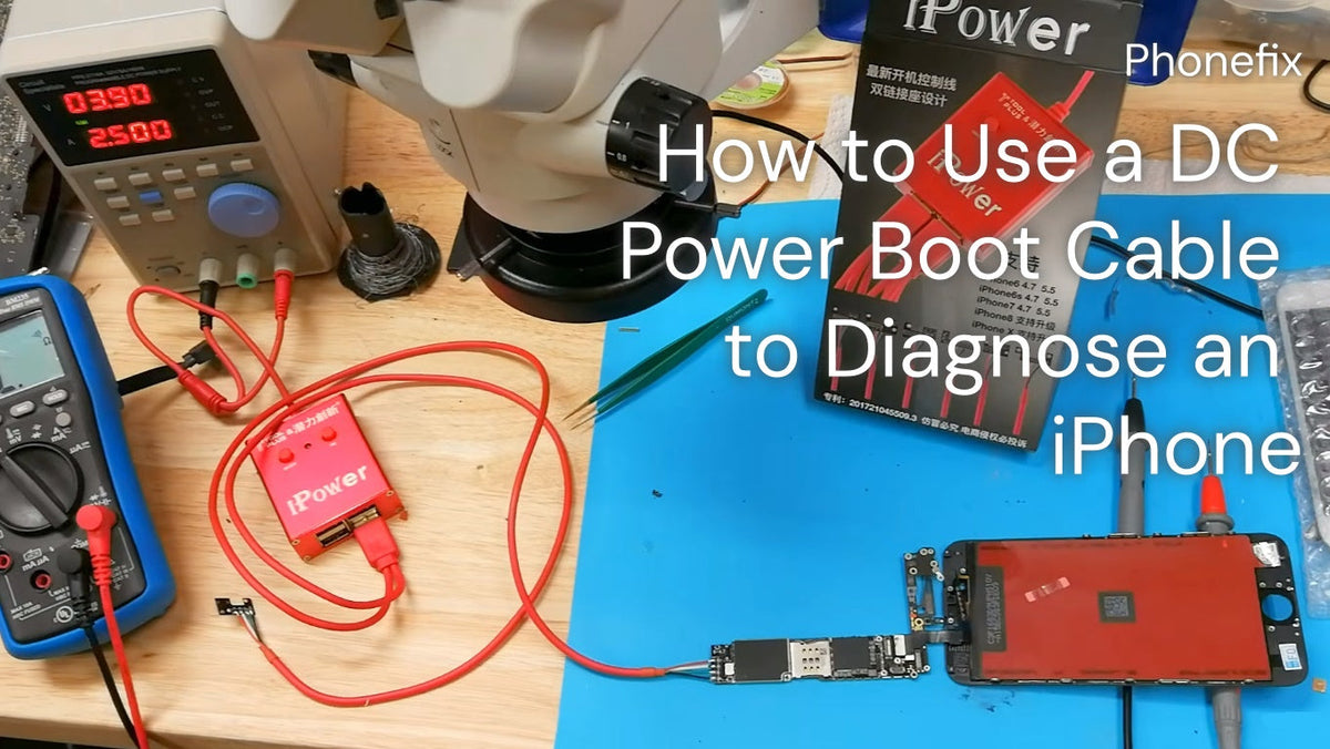
A DC power boot cable is a diagnostic tool, not a repair tool. It supplies controlled power to an iPhone logic board and lets the technician read current behavior on a DC power supply. This guide explains what the cable can and cannot tell, what features a usable cable should have, and how a diagnostic session is carried out.

I. What Can a DC Power Boot Cable Help Determine on an iPhone?
A DC power boot cable is connected in place of the battery, so the logic board can be powered without a battery and without the power button circuit. The tool is used to observe current draw under known voltage. It does not repair the board.
It helps determine the following:
· Whether the logic board shows any current response when power is applied.
· Whether current is drawn before the power button is triggered, which indicates a primary short or leak.
· Whether a boot trigger produces a measurable current jump.
· Whether the current pattern is consistent with a board that is entering a boot sequence.
· Whether a no-boot condition is more likely located on the logic board or in external parts such as the battery, charge port flex, or power button flex.
The cable narrows the fault location. It does not replace diode-mode measurements, visual inspection, or component-level troubleshooting on the PP_VCC_MAIN and PP_BATT_VCC rails.
II. What Is a DC Power Boot Cable and What Features Should a Usable Cable Have?
A DC power boot cable is a short adapter cable. One end connects to a bench DC power supply, usually through banana plugs or similar terminals. The other end snaps onto the battery connector on the iPhone logic board, or onto designated power pads on boards where the battery connector is not used for bench powering. The boot cable sends power directly to the board’s battery input, bypassing the battery and the external power path.
A cable suitable for iPhone diagnostics should meet several conditions:
· The connector must match the battery connector or power pad of the target iPhone model. A loose or forced connection can create false resistance and unstable readings.
· The wire resistance should be low, so the current displayed on the power supply reflects the board’s behavior rather than the cable’s own losses.
· The cable should transmit battery identification data or simulate the battery communication protocol when required, so the board does not refuse to boot or fall into a recovery loop for lack of battery information.
· The cable should support the safe operating voltage range of an iPhone battery, approximately 3.8 V to 4.2 V. Some cables include over-voltage cutoff above 12 V, but the cutoff is a backup measure, not a substitute for correct voltage setting before connection.
· The connector housing and flex should tolerate repeated bending without internal breakage, since the cable is handled frequently during bench work.
III. Diagnostic Procedure with a DC Power Boot Cable
The procedure is carried out on a disassembled iPhone with the battery disconnected. A regulated DC power supply with adjustable voltage and current limiting is required. A supply with current limiting is preferred, because a short will cause the voltage to drop and the current to be held at the set limit, which protects both the supply and the board under test.
Step 1
Set the power supply before connection. Set the voltage to the iPhone operating range, typically 4.2 V. Set a current limit appropriate for boot testing. Confirm the polarity of the leads.
Step 2
Connect the boot cable to the power supply. The input terminals of the cable are connected to the output of the DC power supply. The power supply should be off or set to 0 V, 0 A before the board is connected.
Step 3
Connect the cable to the logic board. The output connector is snapped onto the battery connector or the designated VDD_MAIN/VDD_BATT pad and ground pad. The board is powered with no battery and no display or peripheral flexes connected during the initial reading.
Step 4
Observe the standby current before any boot trigger. On a board with no primary short, the supply should show essentially zero current, commonly 0.000 A, before the power button is simulated. Current drawn immediately after connection indicates a primary short or a leak on the battery rail or main rail.
Step 5
Trigger the boot sequence. The power button is simulated by shorting the power button pin on the board or the interposer connector to ground with tweezers, or by using the trigger mechanism built into the boot cable. The current display is watched during and after the trigger.
Step 6
Record the current behavior and disconnect. The current values and the timing of any jumps are noted. The power supply is turned off, and the cable is removed. The reading is then compared with known boot current ranges for the model, and with the results of diode-mode measurements on the main power rails.

IV. Quick Reference and Common Misconceptions
Current draw is interpreted as a sequence, not as a single number. Different iPhone generations show different startup current values. For reference, the starting current of iPhone 6 series boards is approximately 70 mA, iPhone 6s through XS Max approximately 50 mA, and iPhone 11 and 12 series approximately 80 mA. A normal boot sequence produces a series of current steps. On many iPhone models, the current moves through low values around 40 mA, then 80 mA, then higher values as the GPU, display, and other subsystems are initialized. A board that remains at a low constant current without jumps may have a supply or initialization fault.
Common interpretations are listed below:
· Current appears immediately upon connection, before boot trigger: a primary short or leak is present on the battery rail or the main power rail.
· No current change after boot trigger: the trigger path, the power button line, or the early boot circuit is suspect. The board may also be held in a non-boot state by a fault on the main rail.
· Current rises to a value but does not progress through expected steps: one of the early power rails or a bus initialization stage is failing.
· Current pattern matches the known range for the model: the board is at least reaching the early boot stages under bench power. This does not confirm that all functions are working.
Frequent misconceptions should be avoided:
· The boot cable does not repair a board. A board that draws correct current on the bench may still fail after reassembly because of a disconnected flex or a battery communication fault.
· A voltage above the battery range can damage the PMIC or CPU before any protection circuit reacts. The voltage must be set correctly before the connector touches the board.
· A current reading without current limiting can mislead. A short may pull the supply voltage down, and the current value alone will not reveal the fault.
· One current number is not a diagnosis. The sequence and the comparison with the model’s known range matter more than a single reading.
· The boot cable and the motherboard power supply line are not the same thing. The cable is a connection tool; the power supply line is a circuit path on the board that is measured, not replaced.
V. FAQ
1. Does a DC power boot cable repair an iPhone?
No. The cable supplies power and makes current behavior visible. It does not replace a shorted component, restore a broken trace, or correct a battery communication fault. It is a diagnostic aid.
2. What voltage should be set before connecting the cable?
Set the DC power supply to the iPhone battery operating range, approximately 3.8 V to 4.2 V. 4.2 V is commonly used for boot testing. A higher voltage, such as 5 V or 12 V, can damage the PMIC or CPU before any built-in protection responds.
3. Is current limiting necessary?
Yes. A current-limited supply holds the current at the set limit when a short is present and prevents the voltage from remaining at the set value across a low-resistance fault. Without current limiting, the supply and the board may both be damaged.
4. If the board draws current before the power button is pressed, does that always mean the board is shorted?
Not always. Some iPhone models show a brief self-check current after connection. The value and duration must be compared with the known behavior of the model. A sustained current before trigger is a stronger indication of a leak or short than a brief transient.
5. Can the boot cable replace a battery for testing?
The cable replaces the battery as a power source, but it does not replace the battery as a communication device. Some boards require battery identification data to complete a stable boot. A boot cable that transmits or simulates that data can support a fuller boot; a simple power-only cable may allow only early boot stages to be observed.

A DC power boot cable is a bench diagnostic tool for observing current behavior under controlled voltage. It does not repair the board, and its readings must be interpreted as part of a larger diagnostic process that includes rail measurements and external part substitution. Used with correct voltage and current limiting, the cable provides a repeatable first look at logic board power behavior. It belongs in a set of phone repair tools for board-level work, alongside a regulated DC power supply, a multimeter, and model-specific flex and battery substitutes.


