
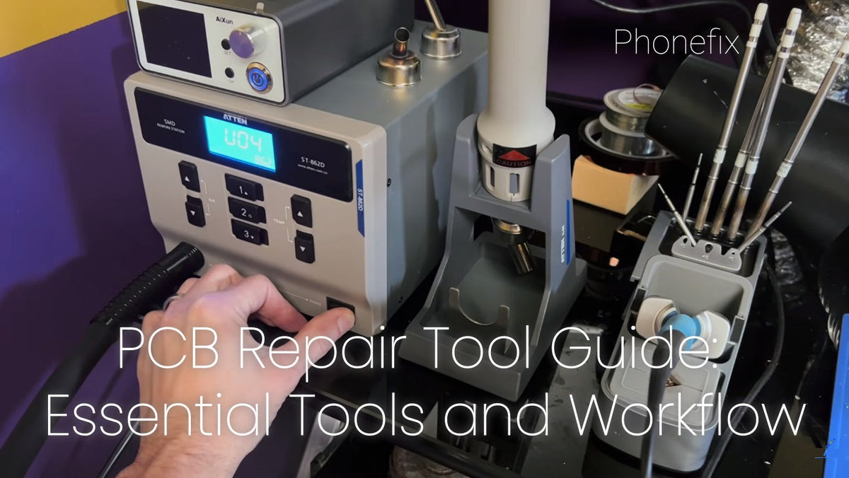
PCB repair is board-level work. It targets faults on the printed circuit board, not just cables or connectors. Many devices fail because of a shorted capacitor, a cracked solder joint, or a damaged trace. This guide covers what PCB repair is, the core tool categories, setup levels, a step-by-step workflow, buying advice, common mistakes, and maintenance practices.
I. What Is PCB Repair?
PCB repair is the process of diagnosing and fixing faults on a printed circuit board. Common faults include cold or cracked solder joints, short circuits, blown components, broken traces, lifted pads, corrosion from liquid damage, and failed ICs, capacitors, resistors, or connectors. PCB work demands precision, heat control, magnification, and electrical measurement. Good tools do not replace skill. They make safe, repeatable repair possible.

II. Core PCB Repair Tool Categories
1. Inspection and Diagnosis
· Microscope: A stereo microscope with 7–45× magnification provides depth perception for soldering. Digital microscopes show a flat 2D image and work better for documentation.
· Digital multimeter: True-RMS and auto-ranging models measure continuity, resistance, voltage, and capacitance.
· Oscilloscope: It traces signals when voltage checks cannot find the fault.
· Thermal camera: It finds shorted components by showing heat patterns.
· Bench power supply: Current limiting allows safe power-up and abnormal current detection.
· LCR meter: It tests capacitors and inductors more accurately than a basic multimeter.
2. Soldering and Rework
· Soldering station: A temperature-controlled station holds heat within ±2 °C on large ground planes. This prevents pad damage and ensures reliable joints.
· Hot air rework station: It removes and installs surface-mount components. Look for closed-loop temperature control, adjustable airflow down to 10–20 L/min, and correct nozzle sizes.
· Preheater: It reduces thermal stress on multi-layer boards.
· Consumables: No-clean flux, 63/37 or SAC305 solder wire, solder wick, and low-melt removal alloy support safe rework.
· Hand tools: ESD-safe tweezers, PCB holders, and Kapton tape improve control.
3. Testing and Programming
· EEPROM programmer: It reads and writes firmware on memory chips.
· USB power meter: It monitors voltage and current during testing.
· Component analyzer: It verifies parts that a basic multimeter cannot test.
· Short-circuit finder: It helps locate low-resistance faults on power rails.
4. Cleaning and ESD Safety
· ESD wrist strap and mat: They prevent static damage to ICs.
· Isopropyl alcohol (99%): It removes flux residue and corrosion.
· Ultrasonic cleaner: It restores boards with liquid damage.
· Fume extractor: It protects the technician from flux fumes.
III. Starter, Intermediate, and Professional Setups
1. Beginner Starter Kit
A basic kit includes a digital multimeter, a temperature-controlled soldering station, a hot air rework station, a PCB holder, flux, solder, wick, tweezers, and a USB microscope. A practice board helps build technique before work on customer equipment.
2. Intermediate Setup
This setup adds a stereo microscope, a bench power supply with current limiting, a preheater, a better hot air station, an ESD mat and wrist strap, and an ultrasonic cleaner. These tools improve speed and safety.
3. Professional Lab
A professional lab uses a BGA rework station, an oscilloscope, a thermal camera, a high-end microscope, an LCR meter, a fume extraction system, and organized component storage. Each upgrade follows a skill milestone.

IV. Step-by-Step PCB Repair Workflow
1. Safety and ESD protection: Wear a grounded wrist strap, use an ESD mat, and disconnect power. Discharge bulk capacitors before touching the board.
2. Visual inspection: Check for burn marks, corrosion, cracked joints, and damaged components under magnification.
3. Power-off resistance checks: Measure continuity and diode voltage across power rails to find shorts before power-up.
4. Powered voltage mapping: If the board powers on, measure voltages at key test points to isolate the faulty section.
5. Signal tracing: Use an oscilloscope to follow signals when voltage readings look normal.
6. Component removal and replacement: Apply hot air or an iron with proper flux and temperature. Use low-melt alloy for stubborn chips.
7. Trace and pad repair: Use jumper wire and epoxy to repair damaged traces and lifted pads.
8. Cleaning: Remove flux residue with IPA or an ultrasonic cleaner.
9. Re-test: Power up with current limiting and verify all functions.
10. Documentation: Record the fault, repair, and replaced parts.
V. How to Choose PCB Repair Tools
Temperature stability matters more than maximum wattage. A station that overshoots its set point can lift pads. Choose ESD-safe construction, auto sleep, and fail-safe airflow shutoff on hot air stations. Mid-range professional units often cost $100–$300 and should carry FCC, CE, and RoHS certification. Check that tips, flux, wick, and nozzles are easy to restock. Spend more on daily tools. Buy budget options for occasional tasks. Leave room for future upgrades such as a preheater or desoldering station.
VI. Common Mistakes and Best Practices
· Do not rework a solder joint that already meets IPC standards.
· Do not press down on the soldering tip. Light pressure is enough.
· Do not raise temperature to solder faster. Higher heat oxidizes the tip and burns flux.
· Use a typical range of 700–770°F with a dwell time of 2–5 seconds.
· Clean flux residue after rework, even when using no-clean flux.
· Diagnose the root cause before replacing parts.
VII. Tool Maintenance and Organization
Clean soldering tips and re-tin them before storage. Replace worn tips, tweezers, and filters. Check air filters monthly if the station has an internal pump. Inspect power cords and connectors for heat damage. Store tools in a dry, dust-free place. Sort components by value and type. Calibrate multimeters and power supplies periodically. Keep a repair log for repeat issues.

PCB repair depends on a balanced toolset. Inspection, soldering, testing, cleaning, and ESD safety tools all play a role. Beginners can start small and upgrade as skills grow. For technicians who want to expand a repair bench, phone repair tools offer a practical next step.


