
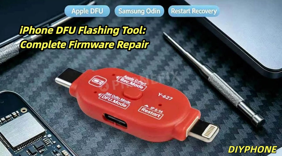
In the mobile phone repair industry, fixing software faults often tests judgment more than hardware replacement. When a device fails to power on normally, gets stuck in recovery mode, or becomes bricked due to an interrupted update, the DFU Recovery Tool becomes the most direct solution. The repair process using it depends not only on the operator's experience, but also on the stability and compatibility of the tool.

I. The Core Value and Prerequisites of DFU Flashing
1. Determining Applicable Scenarios
Not all faults require DFU flashing. When a phone shows a white Apple logo, enters a restart loop, reports error 4013 or 4014, or has a black screen after an update, first try normal recovery mode; if that fails or the device cannot be recognized, then enter DFU mode. Choosing the wrong mode may overwrite user data and cause irreversible loss.
2. Tool Preparation and Data Protection
Before operating, make sure the computer system is clean and the data cable is original or MFi-certified, to avoid interruption of flashing due to unstable power supply. At the same time, use a Digital Multimeter to check the battery voltage - if the voltage is below 3.3V, the device is very likely to lose power midway during flashing. In this case, the battery should first be activated with a DC regulated power supply. Back up user data as much as possible before flashing. Even though DFU usually cannot preserve data, the obligation to inform and the attempt to back up are basic procedures in professional repair.
3. General Steps for Entering DFU Mode
After connecting to the computer, quickly press Volume Up, then Volume Down, then press and hold the Side button until the screen turns off. Next, hold both the Side button and Volume Down for about 5 seconds, release the Side button but continue holding Volume Down for 10 seconds. After successfully entering DFU mode, the screen remains completely black, and the computer will recognize a device in recovery mode. At this point, the flashing tool will indicate that a DFU device has been detected, and you can select a downloaded firmware package for forced writing.

II. Key Points in the Flashing Process
1. Firmware Verification and Writing
When selecting firmware, you must confirm that the model, sales region, and system version all match. Some tools support automatic signature verification; versions whose verification has not been closed cannot be downgraded. During writing, use a USB tester with current detection to observe current fluctuations in real time. Normal DFU flashing current should change steadily between 0.4A and 1.2A. If there is a sudden power drop or the current falls to zero, it indicates a hidden fault in the motherboard power supply circuit, and you should stop flashing and turn to hardware repair.
2. Hardware Indications from Error Codes
When flashing is interrupted, the tool returns an error code. For example, errors 9 or 14 mostly point to abnormal communication between the CPU and the storage chip, while error 4013 is often related to the baseband power supply or storage chip power supply. In such cases, you should not flash repeatedly. Instead, use a hot air gun to heat the motherboard in layers to check for cold solder joints, or use a digital microscope to observe whether chip pins are oxidized. Relying solely on the flashing tool cannot solve hardware-level problems, but the error log provided by the tool is the starting point for locating the fault.
3. Post-Flashing Verification and Finishing
After completion, the device will automatically restart and enter the activation screen. At this point, use a battery health tester to confirm whether the battery cycle count and capacity are normal, so as to prevent sudden shutdowns in later use caused by battery aging. Then run the sensor tests in diagnostic mode to ensure that peripherals such as the gyroscope and proximity sensor have their drivers loaded normally. Finally, leave the device idle for 30 minutes of observation to rule out hidden restarts.

III. Tool Combinations and Efficiency Balance
Various combinations can turn a purely software operation into a comprehensive check of the motherboard's condition.
1. The underlying flashing software is responsible for firmware writing and error log generation, and is the core of the operation.
2. The DC regulated power supply is responsible for providing stable power and simulating the battery state, preventing mid-process power loss.
3. The thermal imaging camera is used during flashing to monitor local temperature rise on the motherboard, preventing overheating caused by short circuits or chip damage.
For example, when the flashing tool repeatedly fails during the baseband firmware writing stage, the thermal imaging camera shows an abnormal temperature rise in the baseband power supply area. Combined with the current overload shown by the regulated power supply, it can be directly determined that the chip is damaged, avoiding the detour of blindly replacing the storage chip or CPU.
The quality of repair tools is not reflected in how many functions they have, but in whether they can provide accurate and stable support at critical moments. Good Mobile Phone Repair Tools are often better able to ensure repair quality.


