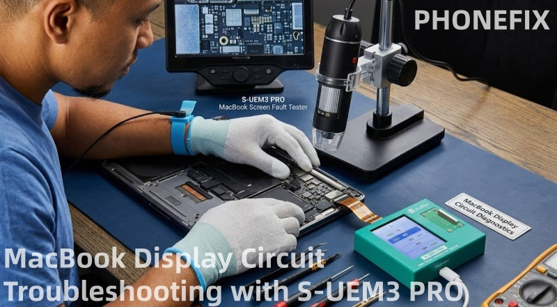
Display failures, backlight malfunctions, and USB-C circuit abnormalities are common challenges in MacBook repair. This article details how to use the S-UEM3 PRO to quickly diagnose display interface and backlight circuit faults in 2016-2025 MacBook Air/Pro models, improving repair efficiency.
I. What is the S-UEM3 PRO Tester?
The S-UEM3 PRO is a professional motherboard interface testing tool designed specifically for Apple laptop repair engineers. It integrates a database of factory-standard diode resistance values for all major MacBook models from 2016 to 2025.
1. Standalone Portable Operation: Equipped with an LED touchscreen display, it can read data directly without connecting to a computer.
2. Full Model Coverage: Supports the entire MacBook Air/Pro lineup, including T1, T2, M1, M2, M3, and M4 models.
3. Multifunctional Comprehensive Testing:
• Type-C Interface Test: Quickly diagnoses 5V-20V voltage boosting failures.
• EDP Display Interface Test: Quickly troubleshoots screen display failures or camera malfunctions.
• JP900/Backlight Interface Test: Precisely locates short circuits or open wires in the backlight circuit.

II. S-UEM3 PRO Dedicated Ribbon Cable Compatibility Guide for MacBook Models
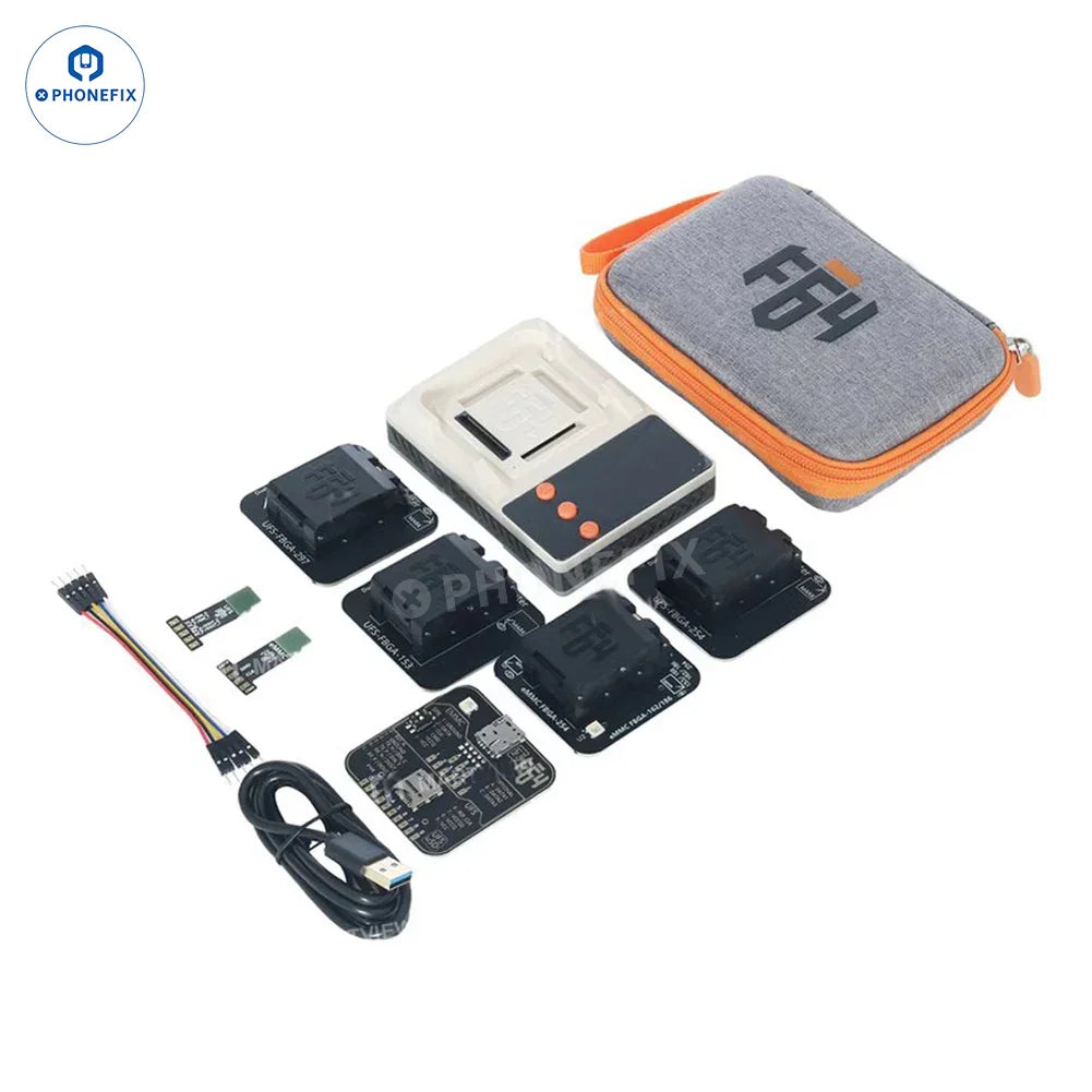
To ensure measurement accuracy, the S-UEM3 PRO comes standard with one adapter board and five dedicated connector ribbon cables. Please select the appropriate ribbon cable according to your MacBook model:
1. J8500/JP600 (48PIN) eDP Ribbon Cable: Suitable for the display interfaces of T1, T2, and M1 models.
2. JP600 (38PIN) eDP Ribbon Cable: Suitable for the display interfaces of M2, M3, and M4 models.
3. A2681/A3113/A3240 JP600 Flex Cable: Applicable to the display interface on MacBook Air M2/M3/M4 models, as well as the right-side USB-C port on T1/T2/M1 models.
4. JP900 Backlight Flex Cable: Applicable to the backlight interface on M2, M3, and M4 models, as well as the left-side USB-C port on T1/T2/M1 models.
5. JP400/JG600/JF600 Flex Cable: Applicable to the camera interface and both the left and right USB-C ports on M2, M3, and M4 models.
III. Four Major Steps for Diagnosing MacBook Display and Backlight Issues Using the S-UEM3 PRO
Step 1: Preparation and Safety Precautions
1. Safety First: Ensure that the MacBook is completely powered off. After removing the laptop's bottom cover, you must first disconnect the battery from the motherboard to prevent accidental short circuits during subsequent operations.
2. Power Supply Setup: Use a standard Type-C cable to connect the S-UEM3 PRO main unit to a 5V power source.
3. Flex Cable Selection: Based on the specific model of the MacBook under repair and the nature of the fault, select the corresponding dedicated test flex cable (for example: if repairing an M2 Pro with a blank screen, select the 38-pin eDP flex cable).
Step 2: Connection and Intelligent Measurement
1. Connect the Flex Cable: Precisely insert one end of the S-UEM3 PRO diagnostic flex cable into the corresponding display/backlight connector on the motherboard (e.g., the JP600, JP900, or eDP socket on the board).
2. Power On the Tester: Turn on the S-UEM3 PRO power switch; the screen will automatically load the built-in factory-standard diode reference values.
3. Analyze the Test Results:
· Normal: The resistance values displayed on the screen for each pin match the reference data exactly, indicating that the signal channels and power rails are functioning normally.
· Short Circuit (0V / Short): The screen highlights the specific pin in red or displays "0V," indicating a severe short-to-ground fault on that specific line. · High/Low Readings: An abnormal resistance value indicates that the capacitor, resistor, or chip connected to this specific pin has degraded in performance or has an open circuit.

Step 3: Using BoardView to Trace the Faulty Component
1. Identify the Faulty Pin: Note down the specific pin number displaying an abnormal reading on the S-UEM3 PRO touchscreen interface.
2. Consult the BoardView: Open your preferred BoardView software (such as OpenBoardView or ZXW) and search for the specific connector socket and the corresponding faulty pin.
3. Tracing Circuits and Chips: Follow the schematic diagram to trace the specific circuit path. For instance, if the backlight enable pin exhibits abnormal behavior, focus your tracing efforts on the backlight driver IC (e.g., UD110), the PMIC (Power Management IC), or the surrounding boost capacitors.
4. Microscopic Inspection and Repair: Under a microscope, examine the circuit line for signs of liquid corrosion, burnt filters, or cracked capacitors. After replacing the damaged component, re-test using the S-UEM3 PRO until the readings for all pins return to normal.
Step 4: Specialized Testing Techniques for Black Screen / No Backlight Issues
If the MacBook powers on normally (indicated by a startup chime and tactile feedback from the trackpad) but the screen remains completely black—or if a faint image becomes visible only when illuminated with a flashlight—this indicates a typical backlight circuit failure.
· Testing Method: Connect the S-UEM3 PRO directly to the JP900 interface (the backlight connector).
· Fault Diagnosis: If the readings for the backlight power rail or the Backlight Enable pin are abnormal, the fault can typically be traced directly to a damaged LED Boost Controller or PMIC. Replacing this specific component will resolve the issue, eliminating the need to blindly apply heat to the entire motherboard.
IV. Frequently Asked Questions (FAQ) Regarding MacBook Chip Repair
Q1: Does the S-UEM3 PRO support the latest M3 and M4 MacBook models?
A: Yes, it does. The S-UEM3 PRO comes pre-loaded with the latest standard interface reference values for MacBook models released between 2016 and 2025, ensuring perfect compatibility with MacBook Air and MacBook Pro models featuring M2, M3, and M4 chips.
Q2: Why does my MacBook screen display a faint image but have no backlight?
A: This indicates a typical failure in the backlight circuit. It is usually caused by a breakdown in the backlight boost capacitor, a blown backlight fuse, or damage to the backlight driver IC. By connecting the S-UEM3 PRO to the JP900 interface, you can quickly identify exactly which line is short-circuited.
Q3: Is it necessary to disconnect the battery when using the S-UEM3 PRO for testing?
A: Yes. Whenever performing motherboard-level resistance measurements or connecting/disconnecting flex cables, you must disconnect the battery first. Performing these operations while the device is powered on carries a high risk of burning out the motherboard's CPU or PMIC chips.
S-UEM3 PRO MacBook Motherboard Interface Fault Detector marks the end of the era of traditional "blind testing." Thanks to its built-in database of standard reference values spanning from 2016 to 2025, it enables repair technicians to intuitively and precisely pinpoint faults related to the MacBook's screen, backlight, and Type-C ports—without any unnecessary guesswork. Whether you are a repair shop owner or a micro-soldering specialist, the S-UEM3 PRO is an essential tool for boosting repair efficiency and reducing rework rates.
Additionally, you may use the following video as a reference for repairs.