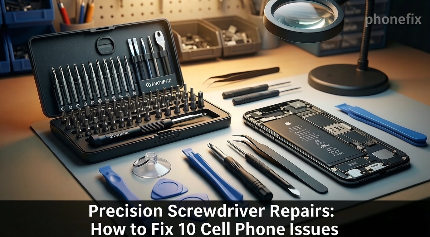
Modern mobile phones are highly integrated devices, yet many of their most frequent hardware failures do not necessitate costly professional servicing or complete device replacement. Malfunctions such as fractured displays, degraded batteries, and unresponsive charging ports can be successfully resolved at home. By utilizing a high-quality Precision Screwdriver Set and a specialized mobile phone repair toolkit from reputable manufacturers like PHONEFIX, individuals can execute precise component replacements. With proper technical instructions, methodical patience, and basic manual dexterity, ordinary users can restore their devices to optimal functionality independently.

I. The Critical Role of Specialized Toolkits
· Attempting hardware adjustments without appropriate instruments frequently results in irreversible secondary damage to the internal architecture of a mobile phone. Standard household tools are entirely unsuited for the micro-components utilized in consumer electronics.
· A professional precision screwdriver set provides exact compatibility with specialized fasteners. Modern smartphones utilize proprietary and diverse screw profiles, including Phillips, Torx, Pentalobe, Tri-wing, and Standoff screws. High-grade driver bits manufactured from S2 steel ensure an exact interface with the screw heads, preventing the stripping of threads or the shearing of delicate components.
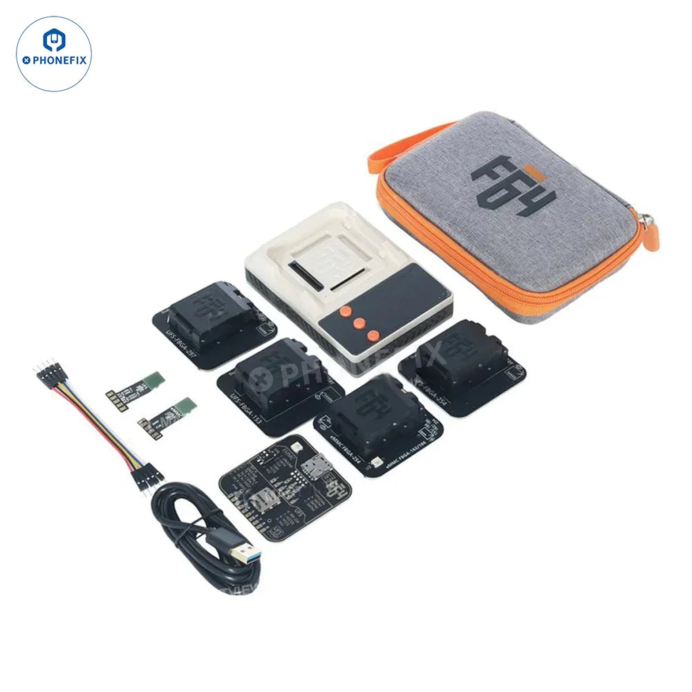
· Furthermore, a comprehensive electronics repair toolkit supplies indispensable auxiliary instruments. Suction cups, ultra-thin plastic opening picks, nylon spudgers, ESD-safe tweezers, and precision pry tools allow users to separate strongly adhered glass panels and release fragile ribbon cable connectors without applying excessive force. These tools safeguard internal circuits against electrostatic discharge and mechanical strain, ensuring a secure opening and assembly process.
II. Ten Repairable Mobile Phone Failures and Technical Procedures
1. Touchscreen and Display Panel Replacement
Step 1: Remove the proprietary security screws located adjacent to the charging port using a Pentalobe or Torx driver.
Step 2: Apply a controlled heat source to soften the perimeter adhesive.
Step 3: Use a suction cup and thin plastic opening picks to carefully separate the display assembly from the chassis.
Step 4: Swing open the panel to expose the internal shield plates, unscrew the retaining brackets, and immediately disconnect the battery cable to prevent electrical shorts.
Step 5: Uncouple the display ribbon cables, connect the replacement panel for testing, and reassemble the device with new pre-cut adhesive water seals.
2. Battery De-aging and Replacement
Step 1: Open the device housing following standard separation protocols.
Step 2: Remove the protective bracket covering the battery terminal and unplug the connector.
Step 3: Locate the high-tensile stretch-release adhesive pull-tabs securing the battery. Wrap them around a pair of tweezers and pull horizontally with uniform tension.
Step 4: If the tabs tear, use a nylon spudger and a few drops of high-purity isopropyl alcohol to safely dissolve the glue and lift the old battery without puncturing it.
Step 5: Install a new cell secured with fresh adhesive tape.
3. Charging Port Module Repair
Step 1: Extract physical debris from the charging port using a non-conductive nylon probe to rule out simple blockages.
Step 2: If the internal contacts are worn or deformed, open the phone to begin module replacement.
Step 3: Remove the lower loudspeaker enclosure or sub-frame assembly to access the component area.
Step 4: Uncouple the flex cable connecting the charging port to the main logic board, along with the coaxial antenna wires.
Step 5: Unscrew the damaged charging port module, lift it from its housing, replace it with an identical OEM part, and re-anchor it firmly.
4. Front or Rear Camera Module Replacement
Step 1: Open the smartphone enclosure and remove the primary EMI shield plates over the logic board.
Step 2: Use a nylon spudger to pop open the press-fit ribbon connectors of the accessible camera modules.
Step 3: Extract the module from its custom recess within the frame.
Step 4: Carefully seat the new camera into the designated slot, taking strict care to avoid touching the glass lenses to prevent oil contamination.
Step 5: Press down firmly on the connector until a physical click is felt, and re-fasten the shielding plates.
5. Internal Loudspeaker and Microphone Restoration
Step 1: Unfasten the Phillips or Torx screws holding the lower loudspeaker box in place. Step 2: Carefully lift the loudspeaker module out of the chassis.
Step 3: Use minimal force to detach the microphone or earpiece components, which are typically attached via light adhesive or spring contacts.
Step 4: Install the new components and ensure the structural seal is properly restored to guarantee acoustic resonance and water resistance.

6. Physical Button Flex Cable Replacement
Step 1: Access the deep interior sides of the phone frame by removing the logic board or adjacent obstruction plates.
Step 2: Unscrew the mechanical brackets holding the exterior physical button keys.
Step 3: Carefully peel away the underlying thin flex cable, which houses the actual electronic micro-switches, from the metal frame.
Step 4: Align the replacement flex cable assembly precisely with the physical buttons and adhere it down.
Step 5: Re-secure the entire setup with its metallic retaining brackets.
7. SIM Card Tray and Card Reader Architecture Repair
Step 1: Inspect the external tray; if it is warped or bent, immediately substitute it with a new mechanical part.
Step 2: If internal spring pins are broken (indicated by a persistent missing SIM error), open the device to inspect the reader module.
Step 3: Locate the SIM card slot on its separate removable daughterboard or flex assembly.
Step 4: Unscrew and replace the entire modular assembly, completely bypassing the need for complex micro-soldering on the main circuit board.
8. Fractured iPhone Back Glass or Phone Back Cover Replacement
Step 1: Apply localized heat at approximately eighty degrees Celsius to the rear perimeter to neutralize the industrial adhesive.
Step 2: Create a minor gap using a suction cup, enabling plastic cards to slide gently along the border. Do not insert tools too deeply to avoid slicing internal wireless charging coils or fingerprint sensor cables.
Step 3: Completely clean any remaining adhesive residue from the structural frame.
Step 4: Transfer any integrated components from the old back cover (such as camera lens covers or sensor brackets) to the new panel.
Step 5: Apply fresh adhesive and press the new rear panel firmly onto the frame.
9. Liquid Ingress Mitigation and Cleaning
Step 1: Power down the device immediately upon accidental liquid exposure to halt electrochemical corrosion.
Step 2: Use the toolkit to quickly open the phone and immediately disconnect the battery. Step 3: Completely remove the logic board from the chassis.
Step 4: Submerge or thoroughly scrub the circuit board with 99% isopropyl alcohol using an anti-static, soft-bristled brush to neutralize conductive mineral deposits and displace moisture.
Step 5: Allow all components to air-dry completely for several hours before performing reassembly and testing.
10. Motherboard Shielding Disassembly and Diagnostic Inspection
Step 1: Use specialized precision drivers to unfasten and remove the metallic electromagnetic interference (EMI) shields from the motherboard.
Step 2: Conduct a close visual inspection of the exposed logic board under a magnifying lens.
Step 3: Check thoroughly for signs of thermal stress, burned integrated circuits, or liquid corrosion indicators.
Step 4: Verify the integrity of board-to-board flex connectors to see if any are loose.
Step 5: Use these diagnostic findings to confirm whether the issue is a simple connection failure or a severe board-level fault requiring professional micro-soldering.
III. Practical Operational Protocols
· Screw Management: Utilize a magnetic project mat or compartmentalized sorting tray to organize every screw chronologically. Installing a screw into the wrong position can puncture lower circuit traces, causing fatal board damage.
· Environment Preparation: Ensure the workspace is immaculately clean, statically grounded, and illuminated with bright, diffused lighting.
· Pre-repair Research: Prior to conducting an unfamiliar procedure, thoroughly review structural teardown videos to understand the exact internal mapping of ribbon cables.
· Tool Integrity: Invest exclusively in high-quality toolkits to protect fragile electronics from tool-inflicted damage.
IV. Potential Strategic Directions
Acquiring mobile hardware repair competencies provides measurable financial and logistical advantages. On an individual level, performing domestic repairs eliminates substantial commercial labor fees and shortens device downtime from days to hours. Beyond personal maintenance, these technical skills can be extended to assist peers, cultivating a local network of reliance.
Over time, mastering these techniques opens up viable entrepreneurial paths. A modest investment in tools can grow into a profitable part-time service, a specialized electronics refurbishing venture, or a dedicated repair enterprise. Many established commercial repair facilities originated from an individual working with a single precision toolset and self-acquired technical knowledge.

Armed with a dedicated precision screwdriver set and an advanced mobile Phone Repair Tool, individuals possess the necessary resources to successfully diagnose and repair ten major hardware faults, including screens, batteries, and charging ports. This technical autonomy reduces personal expenses, builds valuable electronic diagnostic skills, and establishes a foundation for potential commercial enterprises.