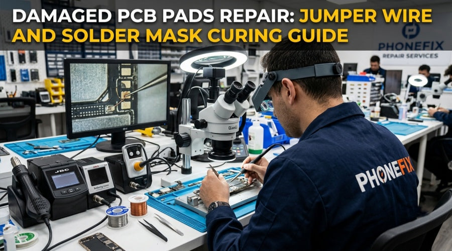
Pad detachment is an extremely challenging failure that can lead to open circuits if handled improperly. However, through standardized jumper wire repair and UV curing techniques, electrical continuity can be effectively restored, and the structural reliability after repair can be enhanced. PHONEFIX will provide a detailed breakdown of the standardized operations for preparation, troubleshooting, implementation, and reinforcement for this process.

I. Pre-repair Preparation and Professional Tool Configuration
The prerequisite for a successful repair is rigorous preparation and precision tools.
1. Work Environment and Safety Guidelines
· Power Disconnection: Operations under power are strictly prohibited. Always remove all main batteries and backup coin cells, and ensure the circuit is at zero potential by measuring the residual voltage of the capacitors.
· Chemical Cleaning: Use high-purity isopropyl alcohol to remove flux residues, grease, and oxides around the damaged area. A clean surface is the foundation for ensuring subsequent solder mask adhesion and soldering strength.
· Electrostatic Protection: A qualified anti-static workbench mat must be used, and an anti-static wrist strap must be worn to prevent electrostatic discharge from damaging the highly sensitive low-voltage signal ICs on the motherboard.
2. Professional Tool List
· Optical Assistance: A Trinocular Stereo Microscope with at least 10x magnification. Observing PCB traces with the naked eye easily leads to misjudgment; a microscope helps you clearly identify the fine copper foil textures beneath the pad.
· Soldering Execution: A precision temperature-controlled soldering station with rapid compensation capabilities. Depending on the board thickness and layer count, precisely control the temperature between 320°C and 350°C.
· Precision Operation: Use specialized anti-magnetic, high-hardness fine-tipped tweezers (such as the Erem or JBC series) for straightening and positioning the wire.
· Pre-treatment Tools: Fiberglass scratch brushes or Swiss precision blades. These tools provide optimal cutting feedback when removing the solder mask to expose the underlying copper foil, avoiding excessive damage to the substrate layer.
· Chemical Consumables: High-purity non-corrosive soldering flux, high-temperature resistant insulated enameled wire, and high-quality UV-curing solder mask.

II. Fault Diagnosis
When a pad detaches, the difficulty of the repair depends on the degree of exposure of the circuit traces.
1. Continuity Testing and Tracing
Use a multimeter switched to continuity or resistance mode to measure the logic connectivity between the damaged pad and adjacent test points. If the pad peels off along with the copper foil, you need to follow the direction of the trace and find the nearest "effective copper point" under the microscope. This is the starting point for the jumper wire.
2. Interface Preparation
· Local Cleaning: Use a blade to slowly scrape off the solder mask layer approximately 1-2 millimeters around the damaged pad. This action must be "steady, accurate, and light"; once you cut other micro-cables nearby, the failure grade will increase exponentially.
· Surface Activation: Exposed copper foil usually has an oxide layer. After applying a small amount of flux, quickly cover it with tin using a soldering iron to form a pre-solder layer. This layer of solder not only serves as protection but also provides a better wetting environment for the subsequent soldering of the enameled wire.
III. Jumper Wire and Circuit Path Reorganization Techniques
1. Enameled Wire Pre-treatment
The surface of the enameled wire is coated with insulating varnish. After cutting to the appropriate length, the insulation layer at both ends must be burned off using the high temperature of the soldering iron tip to reveal the metallic luster. If you use uncleaned wire ends directly, an electrical connection cannot be formed.
2. Precision Soldering Process
· Fixing Point Selection: Solder one end of the enameled wire to the original circuit copper point processed earlier, and precisely lead the other end to the target component pin or the original pad position.
· Stress Relief: During soldering, the jumper wire should have a slight allowance and should not be in a stretched state. The PCB will undergo slight thermal expansion during operation; if the Jumper Wire is too tight, it will easily break from the solder joint after repeated thermal cycles.
· Solder Joint Shaping: After soldering is complete, ensure the solder joint is rounded and free of spikes. Sharp solder joints may penetrate the insulation film during subsequent reassembly, leading to new short-circuit faults.

3. UV Curing and Structural Reinforcement
After electrical connection is completed, the repaired area is fragile. The exposed enameled wire is easily worn by the metal casing or heat sink.
· Insulation Barrier Coating
Apply UV solder mask to the soldering area and the jumper wire path. The solder mask is not only an insulator but also an insulating glue that can firmly fix the fragile jumper wire to the substrate surface, isolating it from moisture and corrosive factors in the external air.
· Curing Procedure
Place the damaged area under a UV curing lamp for 2 to 5 minutes. The solder mask will undergo a polymerization reaction under ultraviolet light, rapidly transforming from a liquid to a hard solid protective film.
· Inspection and Verification
After curing is complete, use a multimeter again to conduct a continuity test. Once you confirm the circuit is connected and there are no short circuits, you can proceed to the final assembly test.
Conclusion
Through precise identification of broken points, standardized jumper wire techniques, and meticulous UV solder mask curing, even severe pad lifting faults can be thoroughly resolved using this guide and professional Mobile Repair Tools. This approach not only reduces the complexity and cost of repairs but also extends the service life of the device. I hope this guide provides you with a systematic framework and operational support for handling high-density PCB trace repairs.