
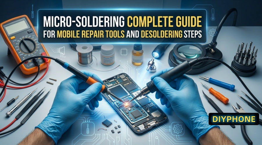
Among all mobile phone repair skills, micro-soldering is one of the most useful. Although it may seem extremely difficult, it is actually a skill that is very easy to pick up. Learning micro-soldering is not as hard as you imagine. DIYPHONE will take you deep into the tools, core circuit principles, and practical operating steps required for chip-level repair of mobile phones, tablets, and computer logic boards.

I. The Differences in Soldering
1. Through-hole Soldering vs. SMD
Basic electronic soldering is mostly Through-hole, meaning the component leads are passed through pre-drilled holes in the PCB and then fixed with solder. This technique is commonly used for repairing large structures such as audio jacks and gamepad buttons.
· However, modern smartphones and tablets pursue ultimate thinness and lightness, and their interiors have long since completely eliminated bulky through-hole components, replacing them with highly integrated SMDs. From chip capacitors and inductors with a size of only 0.1 millimeters to micro IC chips that are easily damaged by heat, all components are surface-mounted directly onto the PCB.
2. Core Challenges of Micro-soldering
In chip-level repair, controlling the position of the soldering iron tip and hot air gun, the precise quantification of solder, the chemical activity of the flux, and the distribution of heat conducted to the circuit board are the keys to determining repair success or failure. With the slightest carelessness, excessive heat may cause internal circuit delamination of the motherboard or solder ball popping of surrounding chips.
3. Basic Theory and Fault Diagnosis
· Electrical Principles and Power Supply: Before using any heating tools, one must understand Ohm's law and the interaction between voltage, current, and resistance. In actual diagnosis, using an adjustable DC Power Supply to power the circuit board is the first step to test the motherboard's current response and locate short-circuit faults. By observing the abnormal jumps of the standby current and boot trigger current, the approximate range of the fault can be quickly narrowed down.
· Schematics and Boardview: A circuit schematic is not a blueprint for copying the device, but a navigation map guiding the flow of signals and power.
a. Reverse Tracking Path: When facing specific faults such as "device not charging" or "no display", technicians can use the schematic to start from the interface end, and trace backwards along the power supply line to protection diodes, filter capacitors, and the main control IC.
b. Layout Localization: Cooperating with the layout, symbols on the schematic can be precisely matched with specific chip positions on the physical motherboard, greatly shortening the trace-finding time.
4. Diode Mode Measurement
When official circuit diagrams are lacking, the ground resistance measurement using the multimeter's diode mode becomes the most core diagnostic method. By connecting the red test lead to the motherboard shield or screw hole, and the black test lead to measure the ground resistance of each power supply and signal line, and comparing it with the resistance data of a known good board, components that are open or short-circuited can be quickly locked down.

II. Key Tools and Consumables Configuration
1. Heating and Soldering Equipment
· Soldering Station: Must be equipped with a high-response micro soldering iron tip, used for cleaning chip pads, jumper wires, and supplementing solder.
· Hot Air Rework Station: Provides a highly concentrated and adjustable air volume of extreme hot airflow, which is the core equipment for desoldering and reflow soldering multi-pin IC chips.
· Preheating Station: Used to perform overall preheating on the entire motherboard, reducing thermal stress caused by local temperature differences, and assisting in the desoldering of large-area heat-dissipating motherboards.
· Thermal Tweezers Soldering Station: Designed specifically for fast desoldering of micro chip capacitors and resistors, capable of achieving simultaneous bidirectional heating on both sides.
2. Observation and Diagnostic Instruments
· Microscope: A good Trinocular Seteo Microscope could povides a microscopic perspective with high definition and comfortable depth of field, paired with a ring LED light source, making 0.1-millimeter-level solder joints clearly visible.
· Digital Multimeter: Equipped with fast diode measurement and milliohm-level resistance measurement functions, used for circuit diagnosis.
· Thermal Imaging Camera: When the motherboard is powered on and short-circuited, by capturing abnormal heating points, it achieves instant localization of short-circuited components.
3. Consumables and Auxiliary Tools
· Chemical Consumables: High-activity neutral flux paste promotes solder flow and prevents oxidation, lead-free low-temperature and medium-temperature solder paste, and fine desolder wick used for cleaning residual solder.
· Physical Auxiliary Tools: High-temperature-resistant motherboard repair fixtures, high-precision anti-static curved tweezers, and insulating paint (such as green oil) used for jumper wire curing protection, and ultra-fine enameled wire which can be used for broken trace repair.

III. Chip Desoldering SOP
1. Pre-Desoldering Preparation Work
· Motherboard Fixation and Protection: Firmly fix the motherboard to be repaired on a dedicated fixture. Use high-temperature-resistant polyimide tape or heat-absorbing stickers to insulate and shield vulnerable components around the operation area, such as camera sockets, plastic connectors, and glue-wrapped chips.
· Applying Flux: Smear an appropriate amount of high-quality flux paste around the target chip. Flux paste not only helps heat conduct evenly, but also removes the oxide layer on the metal surface during the soldering process.
2. Hot Air Gun Parameter Setting
The interior of the motherboard contains multiple layers of copper foil, and copper has extremely strong thermal conductivity. If the heating speed is slower than the rate at which heat dissipates within the circuit board, the temperature of the entire motherboard will rise, causing components on the back to fall off or the motherboard to deform.
· Operation Principle: The heating speed must be faster than the heat dissipation speed. It is necessary to use a hot air gun temperature higher than the actual melting point of the solder, combined with appropriate wind speed for rapid local heating.
· Dynamic Adjustment: Motherboards of different physical sizes, such as thin mobile phone motherboards and thick, large-sized motherboards, have huge differences in thermal capacity. Technicians need to flexibly fine-tune the distance, angle, and dwell time of the hot air gun according to the thickness of the motherboard and the surrounding copper foil area.
3. Chip Removal and Pad Processing SOP
Step 1: Uniform Heating. Position the hot air gun nozzle perpendicular to the top of the chip, maintaining a distance of about 1 to 2 centimeters, and perform circular, uniform movement to heat the chip as a whole and the pads below evenly.
Step 2: Touch Testing. When the flux has completely melted and emits slight smoke, use tweezers to touch the edge of the chip very slightly. If the chip exhibits a soft, elastic floating sensation, it indicates that the solder underneath has completely liquefied.
Step 3: Vertical Gripping. Use tweezers to smoothly clamp the chip vertically upwards away from the motherboard. Avoid forcibly prying when the solder is not completely melted, so as not to pull off the motherboard pads.
Step 4: Pad Cleaning and Leveling. While it is still hot, add a little flux paste to the remaining pads on the motherboard, cooperate with the soldering iron and desoldering wick to gently drag and level the residual solder, and finally use high-purity anhydrous alcohol or PCB cleaner to brush and clean the work area.
IV. Conclusion
For beginners, the best learning path is to collect various discarded old boards and abandoned motherboards, starting from practicing the desoldering of the most basic chip resistors and capacitors, and gradually transitioning to small chip desoldering, BGA reballing, and jumper wire under a microscope. As long as you are equipped with professional Mobile Repair Tools and have mastered circuit measurement methods, you will likewise be able to master micro-soldering technology.


